| | If you imagine a block of granite that a sculptor uses to carve a statue, or planks of wood that are cut and planed from the trunk of a tree, or washing machine lids that are stamped out of a coil of steel, then you have a good idea how traditional manufacturing works. Raw material is reduced or subtracted to form the finished product, and what is left is waste or scrap. Additive manufacturing (AM) works in reverse. Rather than removing material, material is added until the product is completed. The process requires computer technology in the form of computer-aided design (CAD) and manifests itself in several different technologies. The field is rapidly changing and improving, allowing the technology to undertake more roles in production. From chocolate confections to bridges and office buildings, AM is quickly becoming a trusted and economical process in many areas of manufacturing. DEFINITIONAlso known as 3D printing, AM is the process of adding a material layer by layer in the form of a liquid, powder or solid.1 The base material then solidifies into the final shape by some form of heat treatment. Theoretically, waste is reduced to near zero depending on the technology utilized, although excess material may be required to support the solid structure during printing. Complex shapes that once required assembly or further manufacturing can be crafted in a single piece, eliminating additional production steps. AM also allows for the creation of complex geometries and parts that can’t be created with any other process. HISTORYThe history of AM is generally agreed to have begun with the patenting of stereolithography technology in 1984, with the release of the first commercial machine (stereolithography apparatus, or SLA) to use this technology in 1987.2 The most familiar technology is probably fused deposition modeling (FDM) created in 1988. Most home 3D printers today use this technology to melt thermoplastic material from a spool, which is then extruded and layered onto the part being printed. In 1989, the first commercial selective laser sintering (SLS) machine arrived on the market. The SLS machine used a bed of powder as raw material, which interacted with a laser to solidify into the final shape of the finished product.
From these prototypes built in the 1980s, AM technology has steadily grown and improved in quality, cost and speed, and has found its way into myriad industry sectors such as construction, automotive, medical/dental and aerospace. TECHNOLOGIESAll AM processes share three basic steps: 3D modeling, printing the object and post-processing work.1 3D modeling: The object must be digitally modeled using specialized design software. This process typically transforms the image into layers or slivers for rendering. CAD programs are often used for the modeling phase, and the resulting design file is converted into a format that the printing hardware accepts. Printing: Using some form of the technologies discussed in the following section, material is then transformed by heat layer upon layer until the part is finished. Depending on the shape and size of the finished product, some processes require support structures to be printed as well, which are then removed in post-processing. Post-Processing: Depending on the technology, post-processing can include the removal of support structures, rinsing and drying of remaining liquid that still coats the part, or the brushing or air jetting away remaining powder that clings to the final product. The need for this manual step is currently seen as a hindrance for the rapid and inexpensive use of AM for parts production.
The following sections provide some examples of additive manufacturing processes.
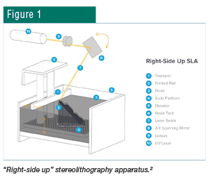
STEREOLITHOGRAPHY APPARATUS (SLA)
Stereolithography is a photochemical process that uses a high-powered laser to harden a bed of liquid resin which is then solidified into a final form. The process converts a photosensitive liquid resin into solid 3D-printed plastic. The resin is photochemically solidified layer by layer until the desired 3D object is completed. A completed part needs to be washed with a solvent to clean wet resin from its surface. The “right-side up” type (Fig. 1) requires that the finished part fit within the polymer tank. Further development resulted in the creation of an “upside down” method which directs the laser from below the tank. This allows the finished product to rise out of the polymer bath and makes it possible to manufacture larger parts. Depending on the shape and size of the part, additional structures may be necessary for support during the printing process.
 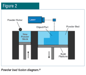
POWDER BED FUSION (PBF), SLS AND SELECTIVE LASER MELTING (SLM)
As the name implies, PBF uses a solid base material in powder form. This powder is spread thin layer, which is then treated with laser melting. Another thin layer of powder is spread on top of the previous layer and the process is repeated. A main advantage of these technologies is the absence of supporting structures to hold up the part during production. The untreated powder surrounds the part and provides the needed support. SLS and SLM are related technologies that differ from each other mainly by temperature. SLM fully melts the base material, whereas SLS heats the powder just until fusion is achieved. Any manufacturing process should first consider the base material and then match the type of AM technology to achieve the desired end result.
ELECTRON BEAM MELTING (EBM)
EBM is most often used in the process of creating metal parts, as the electron beam melts the material in a vacuum at high temperatures (>700°C). This process is similar to the previous SLM method and can produce final products with similar properties. One study using a titanium alloy resulted in a higher surface roughness, and thus more fatigue cracks occurred in the sample created with this method than one created with SLM. The final material properties were generally the same.4
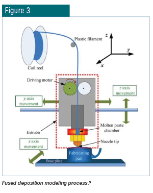
FUSED DEPOSITION MODELING (FDM) OR MATERIAL JETTING
FDM uses plastic filament in a reel or spool that is fed through a heated extruder head onto the part in layers. The print head moves in two dimensions on a horizontal plane layer by layer to create the desired geometry. This technology is used in the most common desktop-sized hobby 3D printers.
 EXAMPLE APPLICATION EXAMPLE APPLICATION
The main advantages of AM technologies compared to conventional processes are their abilities to produce complex geometries, customize parts, shorten lead times and lower the quantity of products. These advantages are useful when ordering repair parts that are no longer manufactured, patient-specific complex designs, and structurally optimized parts with low weight and optimized performance.
One recent example involving steel production is an experiment that attempted to replicate the production of Damascus steel, examples of which can be found in Japanese swordmaking. Of interest in this process is the combination of hardened steel with flexible steel, which, when folded many times in the swordmaking process, produces a very strong but supple final blade.
The metal powder used in the recent experiment was a nickel-titanium-iron alloy steel. The layers with different properties were simulated by turning off the laser for a short period during some of the layers. This action precipitated the rapid cooling of these layers, which were then heated again once the laser resumed. This resulted in steel of different properties throughout the finished part. The results can be seen in Figs. 4 and 5.
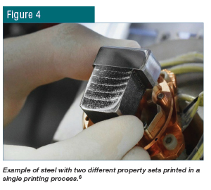 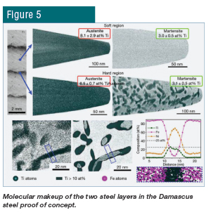
The researchers wanted to demonstrate the control of steel properties at a very fine scale. As a potential application, this technique could lead to the ability to print a tool with a hardened exterior but a more flexible interior. This printing process would eliminate the requirement for more expensive or time-consuming additional heat treatments. SUMMARYAs AM technology matures, the potential applications using steel as a building material continue to increase in efficiency and desirability. An important caveat when evaluating AM as a potential means for the manufacture of steel parts is to heed the differences in time-temperature profiles between traditional manufacturing methods and AM. The details are outside the scope of this introductory article, but suffice it to say that results vary widely at the microstructure level between manufacturing methods, and further heat treatment or alloy design adjustments may be required. Some properties may exceed traditional methods with similar heating recipes, and some properties may not quite attain those found with traditional methods.7
REFERENCES 1. J. Gausemeier, M. Schmidt, R. Anderl, H-J. Schmid, C. Leyens, G. Seliger, P. Winzer, M. Kohlhuber, M. Kage and M. Karg, “Additive Manufacturing,” National Academy of Science and Engineering, 2017, p. 12.
2. https://formlabs.com/blog/history-of-stereolithography-3d-printing/.
3. https://www.lboro.ac.uk/research/amrg/about/the7categoriesof
additivemanufacturing/powderbedfusion/.
4. M. Fousová, D. Vojteˇch, K. Doubrava, M. Daniel and C-F. Lin, “Influence of Inherent Surface and Internal Defects on Mechanical Properties of Additively Manufactured Ti6Al4V Alloy: Comparison Between Selective Laser Melting and Electron Beam Melting,” Materials, Vol. 11, No. 4, 2018, https://www.mdpi.com/1996-1944/11/4/537/htm.
5. https://www.researchgate.net/figure/Schematic-of-fused-deposition-modeling-process-Source-18_fig1_324601411.
6. https://arstechnica.com/science/2020/06/can-you-3d-print-damascus-steel-pretty-much-yeah/.
7. P. Bajaj, A. Hariharan, A. Kini, P. Kürnsteiner, D. Raabe and E.A. Jägle, “Steels in Additive Manufacturing: A Review of Their Microstructure and Properties,” Materials Science and Engineering: A, Vol. 772, 2020, https://doi.org/10.1016/j.msea.2019.138633.
|